


Tools For Developing Zonal Architecture And Software Define Vehicles
Tools For Developing Zonal Architecture And Software Define Vehicles
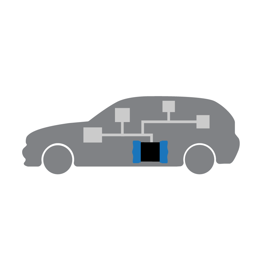
Tools For Developing Zonal Architecture and Software-Defined Vehicles

Choose From A Family Of Loggers To Suit Your Needs
Choose From A Family Of Loggers
To Suit Your Needs
Choose From A Family Of Loggers
To Suit Your Needs
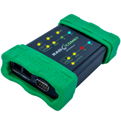
RAD-Comet 2
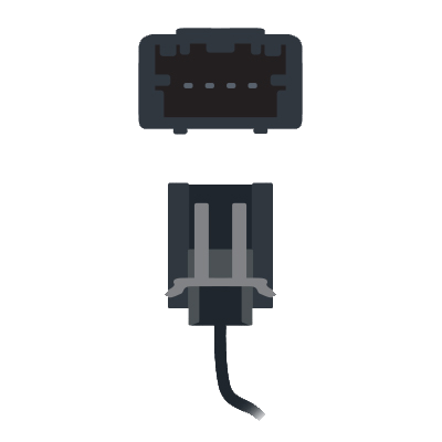
10BASE-T1S Development Interface
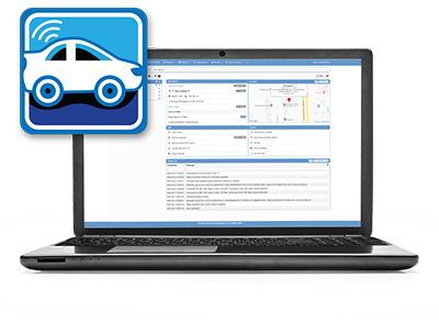
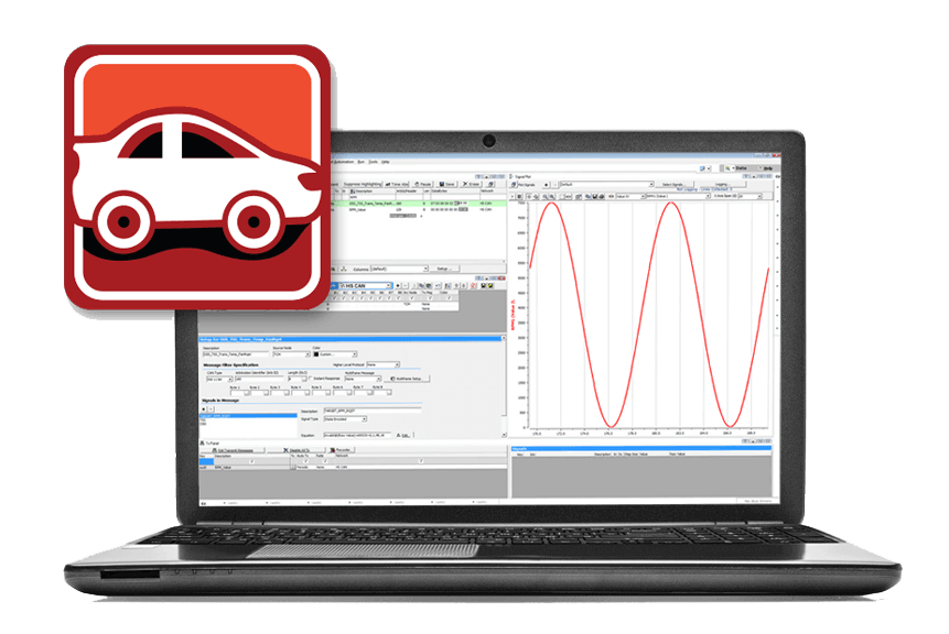
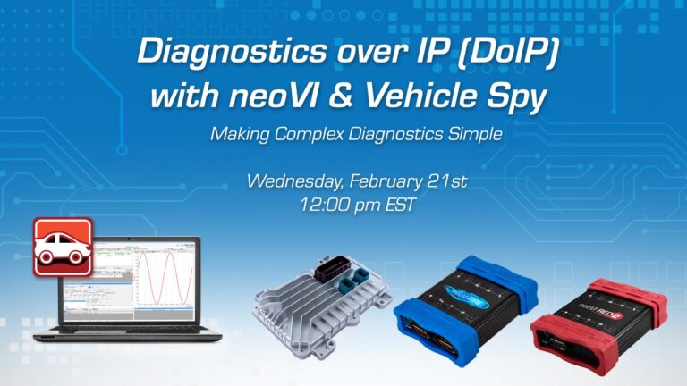
Vehicle Spy: One Tool, Many Tasks.
…now with full Ethernet support and video review!
Diagnostic, Node/ECU Simulation, Data Acquisition, Automated Testing, and more.
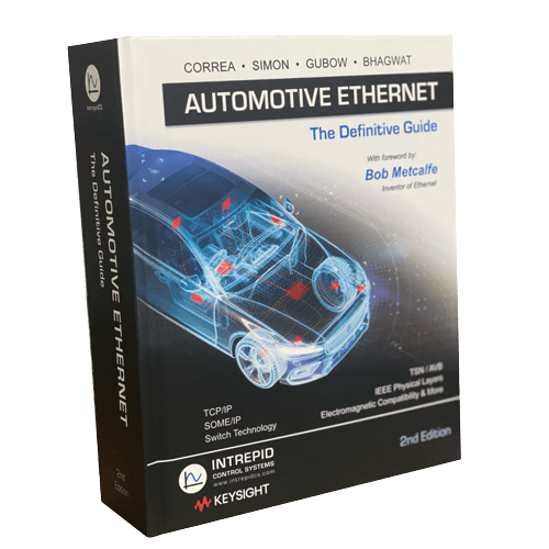
Automotive Ethernet - The Definitive Guide - 2nd Edition (2022)
The Go-To Reference on the Exciting New Technology of Automotive Ethernet!
neoVI PI
Robust and Open Raspberry PI 4 platform for automotive
We Are The Experts
Intrepid was established in 1996, and brings vast knowledge and experience of vehicle networks to provide simple and innovative solutions to your application needs. We provide cutting-edge software and hardware solutions to support various sectors including Automotive, Heavy-duty, Industrial and many more.

Here To Support You
Intrepid is renowned for its customer service, we aim to work closely with our valued customers to support ongoing requirements. To support this, we have state-of-the-art equipment to enable us to manufacture our product solutions within our HQ based in Detroit. Our dedicated teams are ready to support you with your applications and provide technical advice, as well as any training needs.
Unparalleled Experience
Intrepid’s team is created by people like you – from OEMs, Tier 1s, and other experts in automotive vehicle networks. We put all that knowledge into the solutions we provide to you. We continue to expand our experience by keeping engaged with our customers’ projects and participating in key industry committees and working groups.
Universal Vehicle Network Tools
Embedded Data Loggers
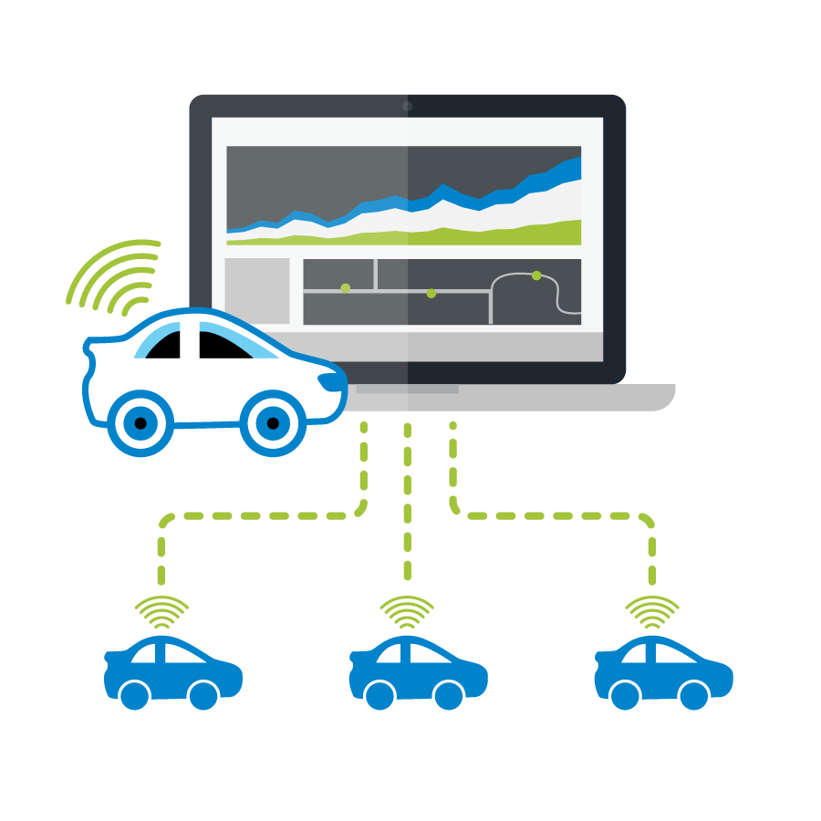
Wireless Fleet Data Logging
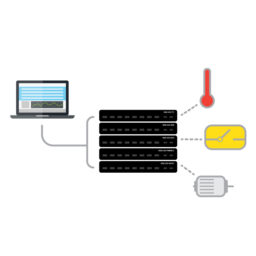
Analog DAQ Devices
The RAD-IO2 series is a family of ruggedized products that provide an isolated analog, digital or temperature interface to a PC via the PC’s USB port. These tools can also be paired with Intrepid products. In addition, the RAD-IO2-CANHUB can power and convert the native UART signal to CAN or CAN FD for use in any CAN device.
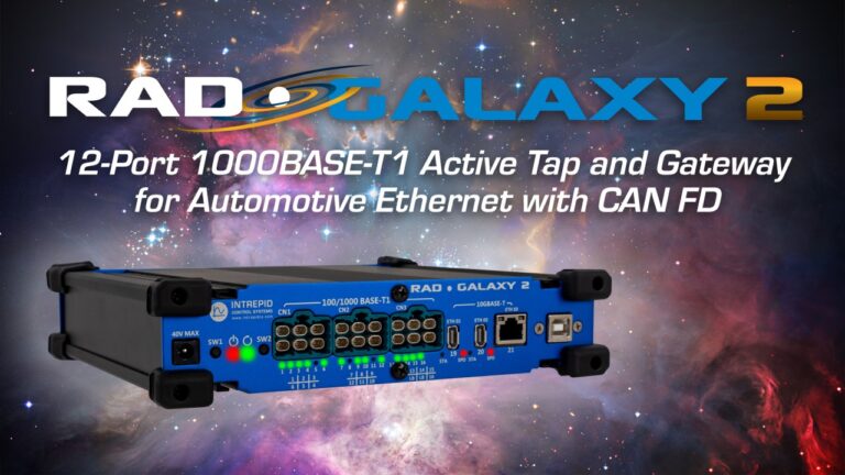
Experiment with Automotive Ethernet
The high speed and bandwidth provided by Automotive Ethernet is enabling the automotive industry to develop increasingly advanced vehicle features such as high-quality audio and video, adaptive cruise control, active lane departure, automatic parking systems, and even fully autonomous vehicles. In response, Intrepid has produced a full line of Automotive Ethernet tools that you can use to easily interface to, simulate and experiment with Ethernet networks. Intrepid’s popular Vehicle Spy software has full Ethernet support.
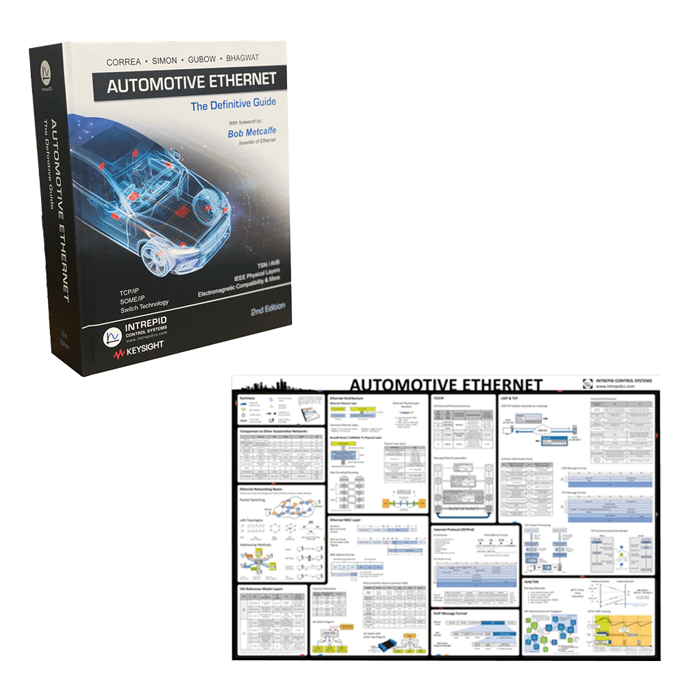
Request a Copy of Our Automotive Ethernet Poster - We'll Send You One Free!
We’ve also published “Automotive Ethernet – The Definitive Guide”, a go-to reference book for Automotive Ethernet, as well as a free, convenient reference poster that covers the basics of this exciting new technology
THE POWER OF PARTNERING


WORLDWIDE REACH
Intrepid has direct offices in most regions of the world to give you the best support possible. We have direct offices in the USA, EU, UK, China, India, Korea, Japan, and Australia.
")
UPCOMING EVENTS & TRAINING
Events
Contact sales to discuss our products and solutions.
- Find the right tools for your application.
- Learn about pricing options
- Access helpful resources
- Training